Both would be drawn with object lines. It is an axonometric projection in which the three coordinate axes appear equally foreshortened and the angle between any two of.
The Language Of Lines Basic Blueprint Reading
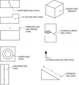
These simple lines play a very important role in the accurate interpretation of engineering drawings.
. That is it is a type of line used. Basic Types of Lines Used in Engineering Drawings By Kelly Curran Glenn Sokolowski. Object line Figure 3 Object lines Hidden lines.
Used to indicate visible object of an object. Thin hidden lines are used as intermittent line types. In engineering drawing practice two principal planes are used to get the projection of object.
A line representing changes of pressure or temperature under conditions of constant volume. 1o a visible edge being represented by a full line and an invisible one by a dotted line ie a line made up of short dashes. The imaginary lines drawn from the object to the plane are called projectors or projection lines.
On the other hand it says that for internal threads. You should specify another point on the construction line. In general application thick lines are 06 mm024.
In oblique projection the object is aligned such that one face front face is parallel to the projection plane. I am refering this Australian drawing standard AS1100 which has shown 2 different line thicknessesweights for hidden lines 018mm 035mm. It has cited an example of a mechanical engineering drawing where it is using a dashed line with 018mm thickness for a hidden line.
They serve as axis lines of symmetrical drawings. Be sure to specify every construction line as needed. Usually terminates with arrowheads or tick markings.
CONSTRUCTION LINE Very light and thin line use to construct layout work. The Language Of Lines Basic Blueprint Reading There are different types of lines used in engineering drawing. It is assumed that an object is placed in front of a screen and light projected on the object assuming that the rays of light to be parallel to each other and perpendicular to the screen then a true shadow of.
The plan on which the projection of the object is taken is called the projection plan. The object may be a point line plane solid machine component or a building. Dashed Thin Lines with Double Dots.
Isometric projection is a method for visually representing three-dimensional objects in two dimensions in technical and engineering drawings. On the home page you can click the Draw Panel Construction Line link. Broken lines that appear in the drawing represent other aspects that are important for you to visualize the object.
Below are the uses of Dashed Thin Lines with Dots. Linetypes And Weight Standards In Technical Drawing. Object lines are used in hand drawing and CAD to define the edges of the view being drawn.
A construction line root can be defined by pointing an object. A quiz completes the activity. In such projection the projectors are not perpendicular to the plane of projection rather inclined to the plane of projection at 30 45.
One can not read a drawing by looking at one view. Note all the lines you find on an engineering drawing are equal. Section line or hatching line.
Definition of isometric line. Thin line with arrows. Used to indicate hidden edges corners hidden in a particular view.
Therefore any surface that is not in line with the three major axis needs its own projection plane to show the features correctly. Dashed Thin Lines with Dots. We will highlight their main functions one by one below.
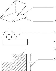
These lines define the shape of the object portrayed and are the outermost outline of the object. Projecting the image of an object to the plane of projection is known as projection. Used to extend the edge face or corner of a geometric feature.
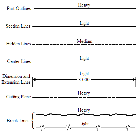
Imagine sketching the front view of a house. 2 The Language of Lines Object Line. DIMENSION LINE Thin and dark lines use to show the size span of an object with a numeric value.
Thick and visible line. It represents an objects physical boundaries. In this highly interactive object learners associate basic line types and terms with engineering drawing geometry.
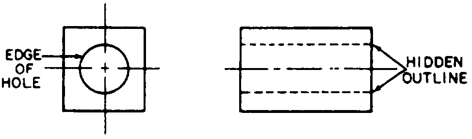
Object lines are solid heavy lines 7 mm to 9 mm. Consider the following illustration to project the image of an object on to a plane. A round bar is shown as a circle in one view and a rectangle in the other.
Only solid lines on the drawing represent visible edges. Thin lines are nearly 03 mm012 in most technical drawings. Many people refer to this as a drawing line.
Engineering Working Drawings Basics Page 8 of 22 parallel to the object surface. There are various options available making it possible to show hidden and visible edges of parts. Use the solid lines to visualize the object in 3-dimensional space.
By pressing Enter the command will be ended. An engineering drawing is a 2-dimensional representation of a 3-dimensional object. Detail Views A detail view is a separate large-scale drawing view of a small section of another view.
They are used as line of symmetry. Construction lines and guide lines are very light easily erased lines used to block in the main layout. These lines are used for the main lengths of the object view.
A visible line or object line is a thick continuous line used to outline the visible edges or contours of. This line is similar to the Dash Thin Lines with Dots except that it has double dots within it. They are used for center lines.
OBJECT OR VISIBLE LINES Thick dark line use to show outline of object visible edges and surfaces. A line such as a contour line drawn on a map and indicating a true constant value throughout its extent. How To Use Construction Lines In Drawing.
A hidden line also known as a hidden object line is a medium weight line made of short dashes about. Many other line types exist and are used to communicate things like interior detail but object lines are the darkest lines on the pagescreen. Centerlines indicate a circular feature on a drawing.
The most common type of line is the continuous line. In 2D most circular features look exactly the same as features with non-circular geometry. A line on a drawing always indicates either an intersection of two surfaces as in the projection of a prism or a contour as in the projection of a cylinder fig.
Line Conventions Manufacturinget Org

Hidden Lines Youtube

What Are Lines Types Of Lines In Engineering Drawing Youtube

Engineering Design And Cad A B Line Types Flashcards Practice Test Quizlet
The Language Of Lines Basic Blueprint Reading
What Are The Types Of Lines In Engineering Drawing Quora
Line Conventions Manufacturinget Org

Engineering Drawing Notes B Drawings Engineering Types Of Drawing
0 comments
Post a Comment